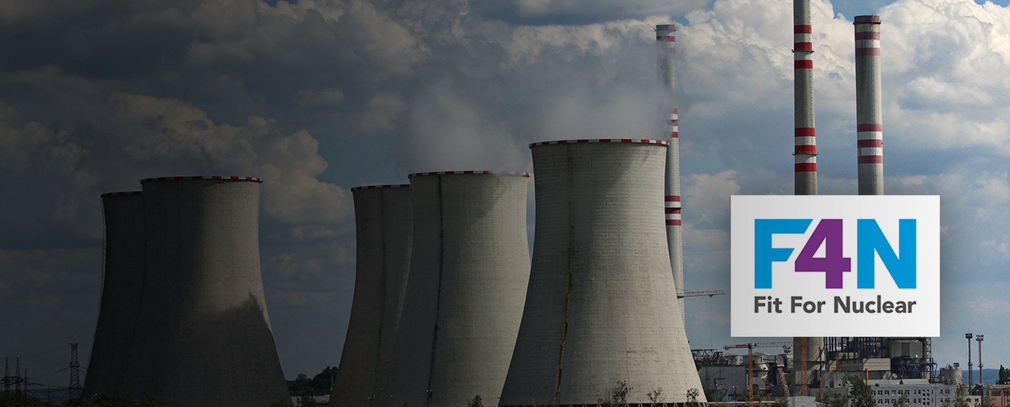
Hawke International Achieves Fit for Nuclear (F4N) Status
We have been granted Fit For Nuclear (F4N) status by the Nuclear AMRC, to officially confirm our capacity to provide for the nuclear industry.
Read our blog to find out more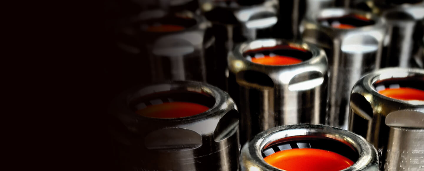
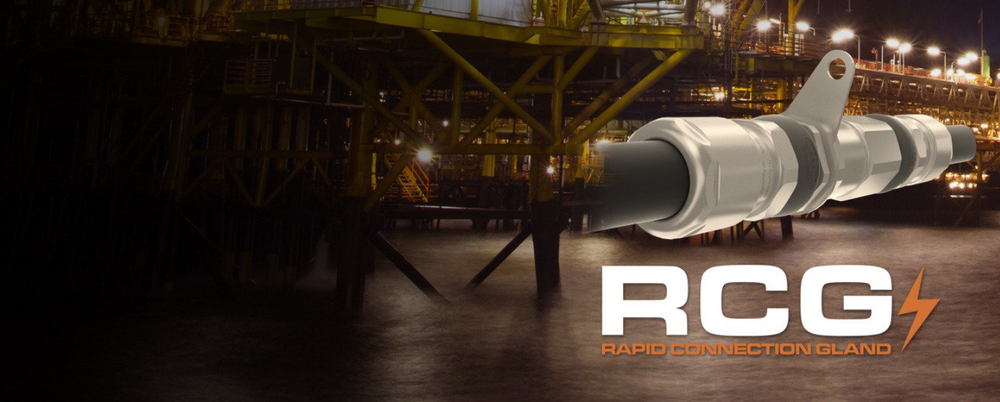
Just arrived! The new Cable Glands catalogue
Our long awaited Cable Glands &Accessories catalogue has been launched with many updates and new product information. Now available to download.
Download NowIn need of an easier barrier gland installation?
Our new and improved PSG/553/RAC and SB/474 are here.
Find Out More